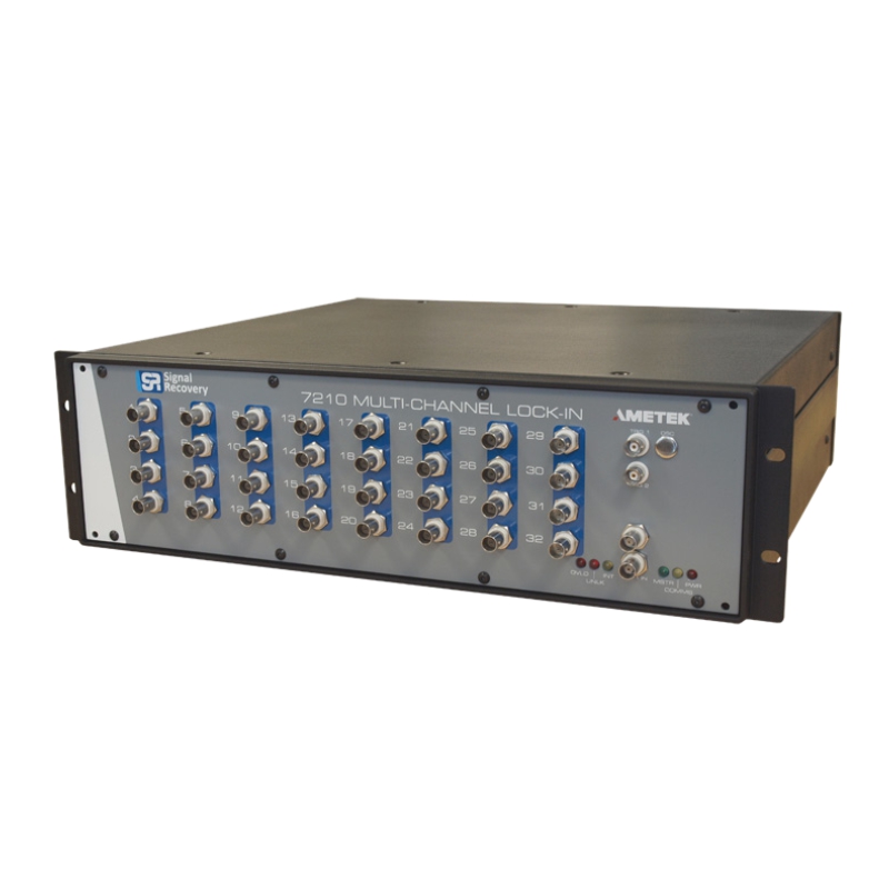
The design concept of the Model 7210 revolves around the idea of a single excitation signal combined with a multitude of detectors. So, the Model 7210 represents an economical solution compared to using a multitude of expensive amplifiers to work with each detector.
The main features & specification points are:
- Each unit can be configured with 4, 8, 12, 16, 20, 24, 28, or 32 input channels
- Up to sixteen units can be chain-linked together, giving up to 512 input channels
- Operates with an external reference only
- Software controlled, without a front panel
- Measured outputs are recorded digitally
- Currently offer one type of signal input card:
- Model 7210/99 option, which is a Voltage Input card
- Operates at frequencies between 20 Hz & 50.5 kHz
- Sensitivity range of 100 uV to 1 V
- Two choices of software solution:
- SR7210Comms, which is an ActiveX software development toolkit
- MULTILCOK software for a complete data acquisition solution (which includes SR7210Comms)
Click below to download:
The signal input specifications depend on the type of signal board fitted, of which one option is currently available:
7210/99 Signal Board – Voltage Mode Inputs
| Voltage Input |
| Input Mode |
Virtual Ground |
| Connector |
BNC |
| Impedance Shell to Ground |
0 Ohms |
| Input Impedance |
10 M Ohms |
| Input Voltage Noise |
< 10 nVHz-0.5at 1 kHz |
| Max Safe Input |
± 12.0 V |
| Frequency Response |
20 Hz to 50.5 kHz |
| Typical Gain Accuracy Overall |
± 1.5% |
| Typical Gain Match between Channels |
± 3.0% |
| Phase Accuracy Overall |
± 2° |
| Phase Match between Channels |
± 1° |
| Full-scale sensitivity |
100 µV to 1 V rms in a
1-3-10 sequence
(9 settings) |
| Reference Channel |
| External Reference Input only |
|
| Impedance |
1 M Ohms//35 pF |
| Level |
250 mV to 2.5 V rms |
| Connector |
BNC |
| Frequency Range, F1 |
20 Hz to 50.5 kHz |
| Lock Acquisition Time |
2 sec (max) |
| Reference Phase Shifter (each channel) |
Set Resolution 10 m°
Orthogonality 90° ± 0.001° |
| External Reference Frequency Meter Resolution |
1 Hz |
| Reference Output (Tandem frequency), F2 |
|
F2 is F1/n, where n, an integer, is calculated by the instrument to give a frequency as
close as possible to a user-specified value in the range 0.001 Hz to 100 Hz |
| Amplitude |
> 3 V pk-pk square-wave |
| Impedance |
< 200 Ohms |
| Connector |
BNC |
| Harmonic DetectionF and 2F |
| 2F (available in single-frequency operation only) |
2F < 50.5 kHz |
| Meter Resolution |
0.001 Hz |
| Demodulator |
|
| Main ADC’s, each channel |
12 bit |
| Sampling Rate |
208 kHz < fs< 250 kHz,
synchronous to external reference (F1) frequency |
| Single-Frequency Operation |
| Time Constants |
4 ms to 1 ks in 1-3-10 sequence (12 steps) |
| Slope |
12 dB/octave |
| Type |
Synchronous digital FIR filters |
| Harmonic Rejection |
> 90 dB |
| Dynamic Reserve |
> 80 dB |
| Tandem-Frequency Operation |
| Applying to F1 outputs: |
|
| Time Constants |
4 ms to 1 ks in 1-3-10 sequence (12 steps) |
| Slope |
12 dB/octave |
| Type |
Synchronous digital FIR filters |
| Harmonic Rejection |
> 90 dB |
| Dynamic Reserve |
> 80 dB |
| Applying to F2 outputs: |
|
| Time Constants |
30 ms to 1 ks in 1-3-10 sequence (11 steps) |
| Slope |
12 dB/octave |
| Type |
Synchronous digital FIR filters |
| Harmonic Rejection |
> 90 dB |
| Dynamic Reserve |
> 80 dB |
| Data Outputs |
| The outputs available from the instrument are: |
|
| Single Reference Mode |
X1 and Y1 |
| Tandem Demodulation Mode |
X1, Y1 and X2, Y2 |
All outputs are for each of 32 channels. Outputs can be read directly on receipt of a command, or stored on receipt of a GPIB trigger or the GET command for later readout. The output values can be read using commands generating binary or ASCII responses.
Interconnections
Instruments can be interconnected to provide more than 32 detection channels. Interconnections are via RG45 multipole connectors. Each instrument has a rear-panel switch to select whether the connectors function as outputs, in which case the unit is the “master”, or inputs, when the unit is a “slave”.
| Indicators |
| Front-panel LEDs indicate the following conditions: |
|
| Power On |
a single LED which is lit when line power is applied and the unit switched on |
| Communications Activity |
indicates when command is being received and response is waiting to be read or being transmitted |
| Master/Slave |
when lit indicates that the instrument is set to function as a “master” and that its synchronizing signal connectors are configured as outputs |
| Internal Oscillator |
reserved for future expansion |
| Reference Unlock |
lights when no suitable reference is applied |
| Signal Channel Overload |
a single LED warning of input or output overload in any one of the 32 channels. It is possible to identify via a computer status command which channel(s) is affected and the type of overload condition |
| General |
| Computer Interfaces |
GPIB (IEEE-488)
and RS232 |
| Connectors |
Standard GPIB Centronics connector and
9-pin female RS232 |
| Comms Settings |
Set by rear-panel DIPswitches |
| Command Set |
ASCII commands for all instrument controls and data readout.
Binary dump commands for data readout |
| Power Requirements |
| Voltage |
100/120/220/240 V AC |
| Frequency |
50 – 60 Hz |
| Power |
200VA max |
| Dimensions |
| Width |
446 mm |
| Height |
3U (133.5 mm) |
| Depth |
435 mm |
| Weight |
12.5 kg |


There are no reviews yet.